Audio Mixer Circuit Part: Build Your Own Mixing Console! One-transistor audio mixer circuit diagram
Alright, let's dive into the exciting world of audio mixers! Whether you're a seasoned audio engineer or just starting out with your home studio, understanding how these devices work under the hood can be incredibly valuable. I've been digging around and found a couple of interesting diagrams that I thought I'd share, offering a peek into the inner workings of audio mixing circuits.
8 Channel Audio Mixer Circuit Diagram

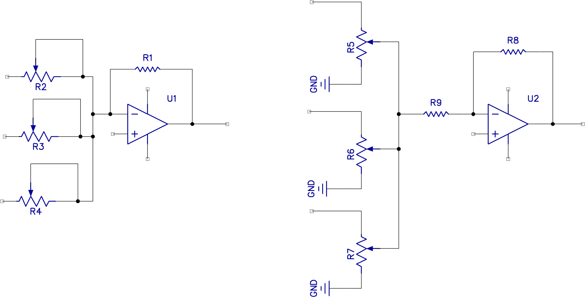
This diagram represents a pretty standard 8-channel audio mixer setup. What immediately catches my eye is the modularity – you can clearly see how each channel is essentially its own mini-circuit, contributing to the overall mixed output. This allows for independent control over each input source. You'll notice potentiometers (the knobs we all love to tweak!) being used for gain adjustment at each channel. These allow you to control the level of each input signal before it's summed together. The resistors and capacitors dotted around are crucial for shaping the audio signal and ensuring a clean, balanced sound. Look closely, and you'll probably spot op-amps (operational amplifiers) at various stages. These are the workhorses of the circuit, amplifying the signals while maintaining their fidelity. Understanding the function of each component, like the resistors ensuring correct current flow or the capacitors filtering unwanted noise, can really help you appreciate the complexity of even seemingly simple audio devices. Think about the implications of changing resistor values - a slight modification could significantly alter the gain structure or EQ characteristics of a particular channel.
Diy Audio Mixer Schematic

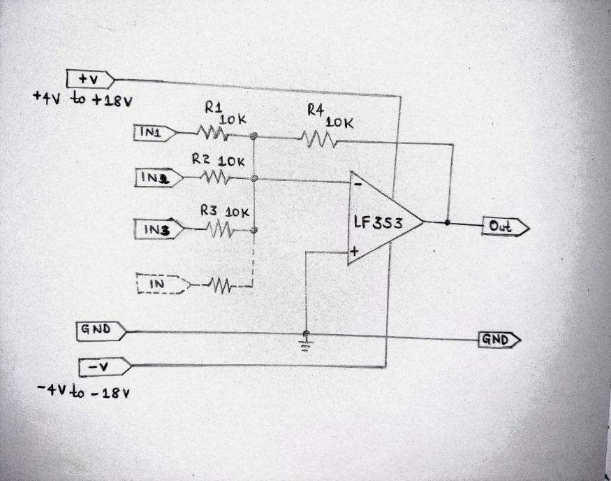
Now, this schematic offers a glimpse into a DIY audio mixer project. While it might look a bit intimidating at first, breaking it down reveals the fundamental building blocks. One of the key things to observe here is how multiple input signals are combined. In a typical DIY mixer like this, you'll find a common summing amplifier stage, where all the individual channel signals are added together. Before reaching this point, each channel usually has its own pre-amplification and level control circuitry. This allows you to adjust the volume of each input individually. Notice the components associated with each channel – these often include potentiometers for gain control, resistors for setting bias currents, and capacitors for filtering and coupling signals. Building something like this yourself gives you an unparalleled understanding of how each part contributes to the final sound. It can be a fantastic learning experience, allowing you to experiment with different components and circuit configurations. Imagine tweaking the feedback resistor in the op-amp circuit – you'd instantly hear the effect on the gain and potentially the overall tone. Furthermore, having built your own mixer allows you to customize it precisely to your needs, something you simply can't do with off-the-shelf products. You could add specific EQ controls for certain channels, incorporate custom effects loops, or even experiment with unique gain staging techniques. It's all about building something that perfectly fits your unique audio workflow!
If you are looking for High-Level 4-Channel Audio Mixer Circuit Diagram you've visit to the right place. We have 25 Images about High-Level 4-Channel Audio Mixer Circuit Diagram like High-Level 4-Channel Audio Mixer Circuit Diagram, Mixing Circuit Diagram - Circuit Diagram and also Audio Mixer Schematic » Wiring Way. Here it is:
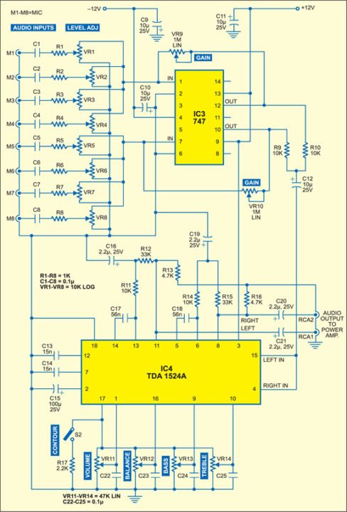
High-Level 4-Channel Audio Mixer Circuit Diagram
 www.pinterest.com
 High-Level 4-Channel Audio Mixer Circuit Diagram
Audio Mixer Schematic » Wiring Way
 www.wiringway.com
 Audio Mixer Schematic » Wiring Way
Simple Audio Mixer Schematic Diagram - Circuit Diagram
 www.circuitdiagram.co
 Simple Audio Mixer Schematic Diagram - Circuit Diagram
How To Build An Audio Mixer Circuit: A Step-by-Step Guide
 design1systems.com
 How to Build an Audio Mixer Circuit: A Step-by-Step Guide
Audio Mixer Circuit
 bestengineeringprojects.com
 Audio Mixer Circuit
Building An Audio Mixer With PCB Design: A Step-by-Step Guide
 diagramio.com
 Building an Audio Mixer with PCB Design: A Step-by-Step Guide
Operational Amplifier - Audio Mixer Circuit With Individual Volume
 electronics.stackexchange.com
 operational amplifier - Audio Mixer Circuit with Individual Volume ...
Voltage Controlled Audio Mixer Circuit - ElectroSchematics.com
 www.electroschematics.com
 Voltage Controlled Audio Mixer Circuit - ElectroSchematics.com
8 Channel Audio Mixer Circuit Diagram
 circuitbebsonir.z13.web.core.windows.net
 8 Channel Audio Mixer Circuit Diagram
Audio Mixer Circuit
 www.circuits-diy.com
 Audio Mixer Circuit
One-Transistor Audio Mixer Circuit Diagram - TRONICSpro
 tronicspro.com
 One-Transistor Audio Mixer Circuit Diagram - TRONICSpro
Simple Audio Mixer Circuit Diagram
 www.circuitdiagram.co
 Simple Audio Mixer Circuit Diagram
Audio Mixer Circuit Diagram Using Transistor - Circuit Diagram
 www.circuitdiagram.co
 Audio Mixer Circuit Diagram Using Transistor - Circuit Diagram
Audio Circuit Mixer: 5 Ways Of Building An Audio Mixer
 www.wellpcb.com
 Audio Circuit Mixer: 5 Ways of Building an Audio Mixer
Mixing Circuit Diagram - Circuit Diagram
 www.circuitdiagram.co
 Mixing Circuit Diagram - Circuit Diagram
Designing An Advanced Circuit For Professional Audio Mixing
 techdiagrammer.com
 Designing an Advanced Circuit for Professional Audio Mixing
Audio Mixer Overview - AudioFusion
 audiofusion.com
 Audio Mixer Overview - AudioFusion
Audio Mixer Circuit Diagram With Pcb Layout
 www.circuitdiagram.co
 Audio Mixer Circuit Diagram With Pcb Layout
Basic Audio Mixer Using Op-Amp – Simple Circuit Diagram
 www.simplecircuitdiagram.com
 Basic Audio Mixer Using Op-Amp – Simple Circuit Diagram
4 Microphones Mixer Circuit Diagram - Circuit Diagram
 www.circuitdiagram.co
 4 Microphones Mixer Circuit Diagram - Circuit Diagram
6 Channel Audio Mixer Circuit Diagram
 schematicmotorumbasic.z4.web.core.windows.net
 6 Channel Audio Mixer Circuit Diagram
LM3900 Audio Mixer Circuit
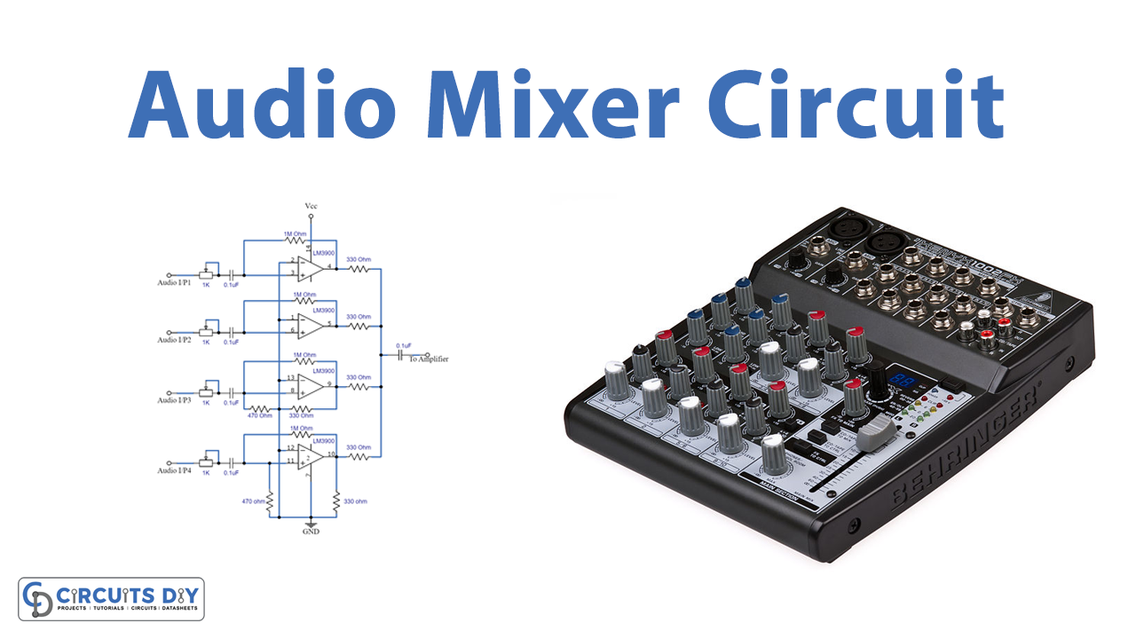 www.circuits-diy.com
 LM3900 Audio Mixer Circuit
Mixer Audio Circuit Diagram
 www.circuitdiagram.co
 Mixer Audio Circuit Diagram
Digital Audio Mixer Circuit Diagram - Circuit Diagram
 www.circuitdiagram.co
 Digital Audio Mixer Circuit Diagram - Circuit Diagram
Diy Audio Mixer Schematic
 circuitheilsumtm.z14.web.core.windows.net
 Diy Audio Mixer Schematic
Audio mixer circuit diagram with pcb layout. Operational amplifier. High-level 4-channel audio mixer circuit diagram